Overview
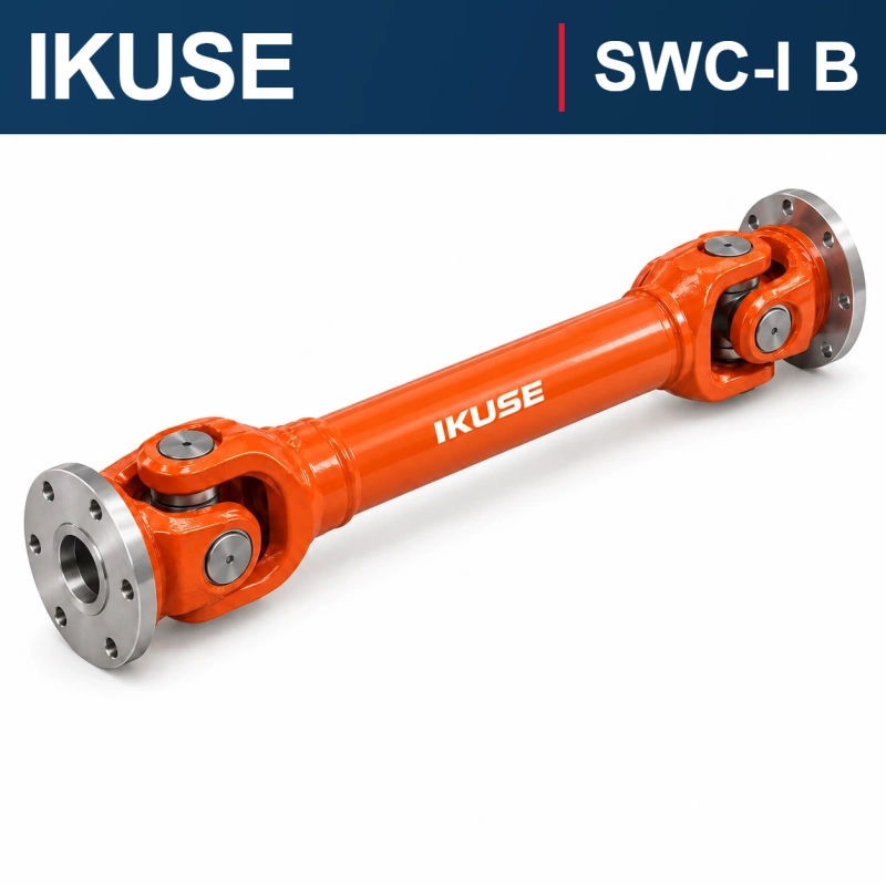
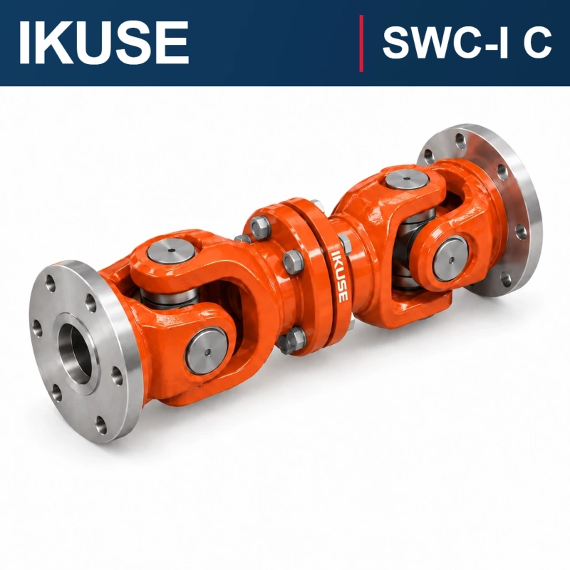
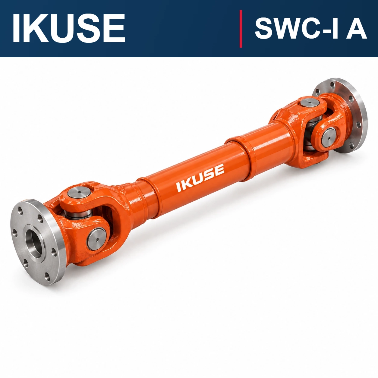
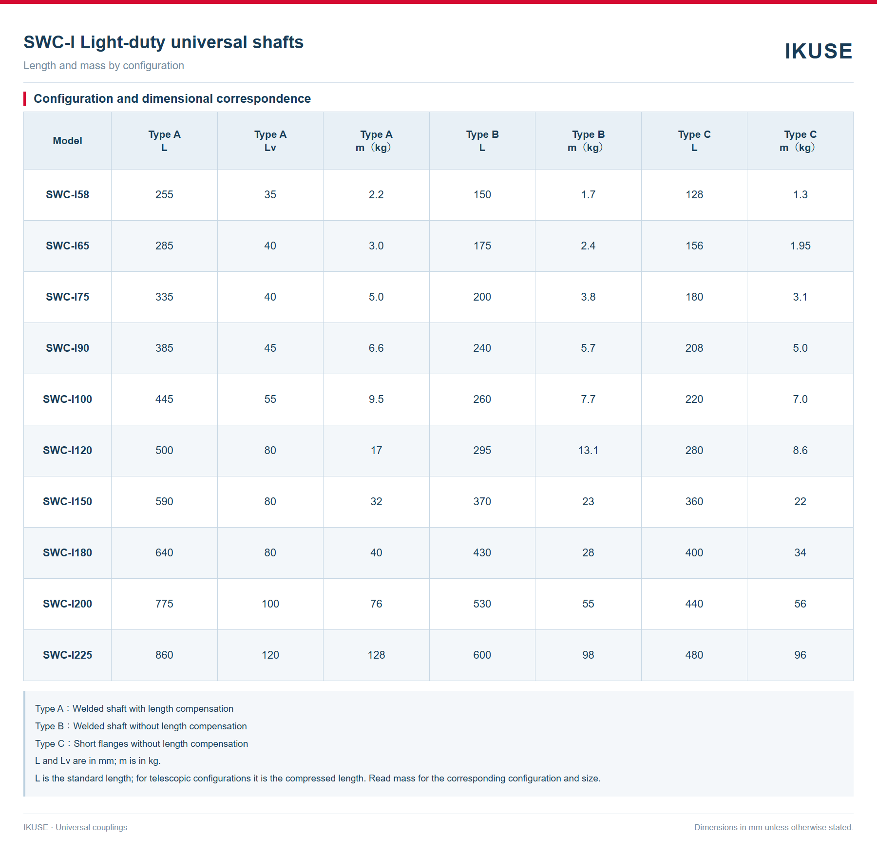
SWC-I A — Welded shaft with length compensation. Transmits torque between shafts arranged at an angle. Length compensation is provided; select the installation length for the equipment.
Construction
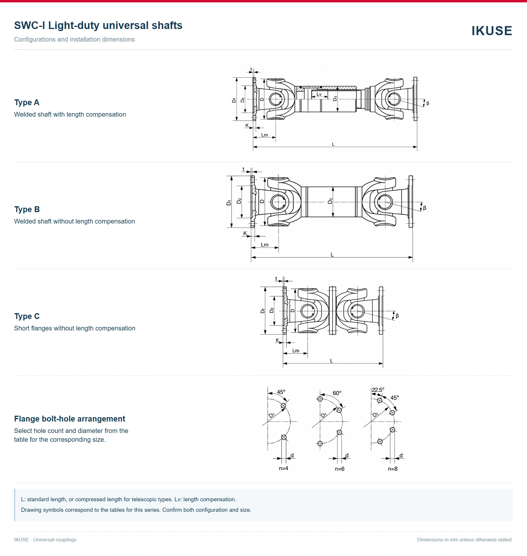
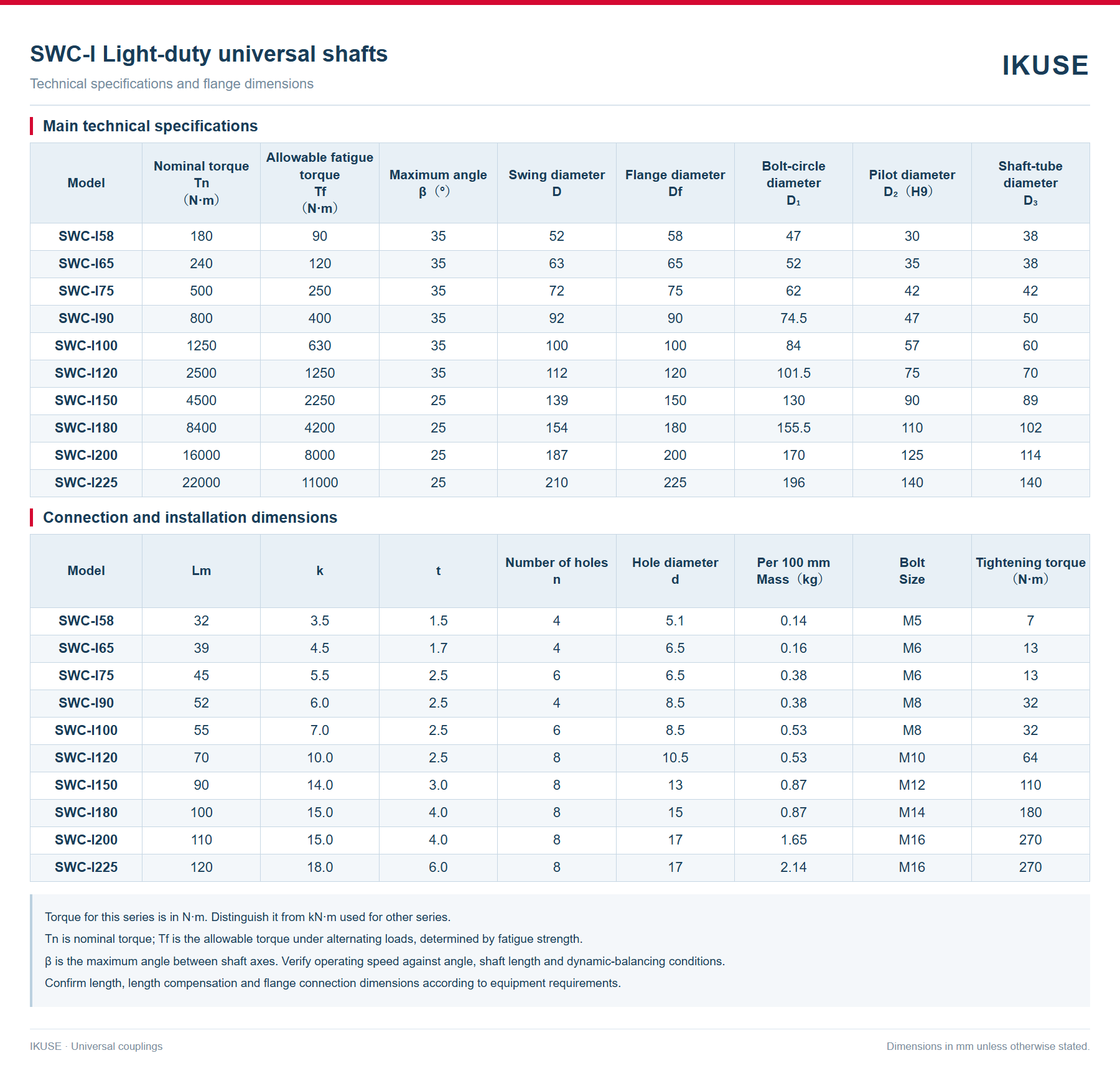
Crosses in two universal joints transmit torque between angled shafts. Welded shaft with length compensation. L is the compressed length and Lv the length compensation. Select flange pilots, bolt circles, hole diameters and hole counts for the same size. Check maximum angle β and operating speed against shaft length, load and balancing conditions.
Applications
Light-duty drives requiring angular accommodation between shafts. Consider power, speed, changing loads, available space and flanges.
Technical specifications
Nominal torque Tn and allowable fatigue torque Tf are in N·m. Dimensions are in mm unless otherwise stated. Use the rows for the selected configuration; do not mix dimensions from different configurations.
Installation and maintenance
Check both flanges, connecting bolts and shaft arrangement during installation. Tighten according to the selected size. Inspect for loose fasteners, unusual vibration, noise and lubrication condition. Set lubrication and maintenance intervals according to actual duty.
Ordering information
Specify equipment type, power, operating speed, operating and peak torque, load characteristics, shaft angle, installation length, required length compensation and dimensions of both flanges. Include ambient temperature, balancing and protection requirements.