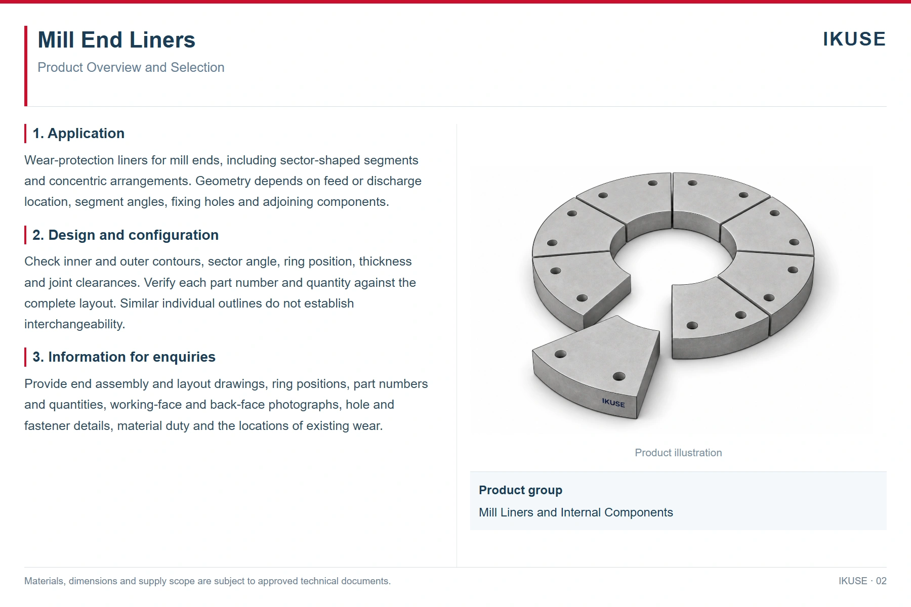
Product overview
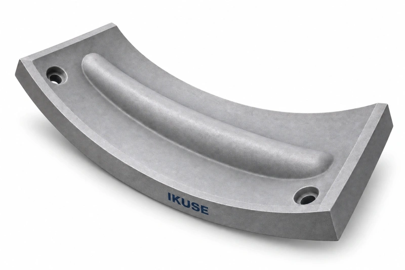
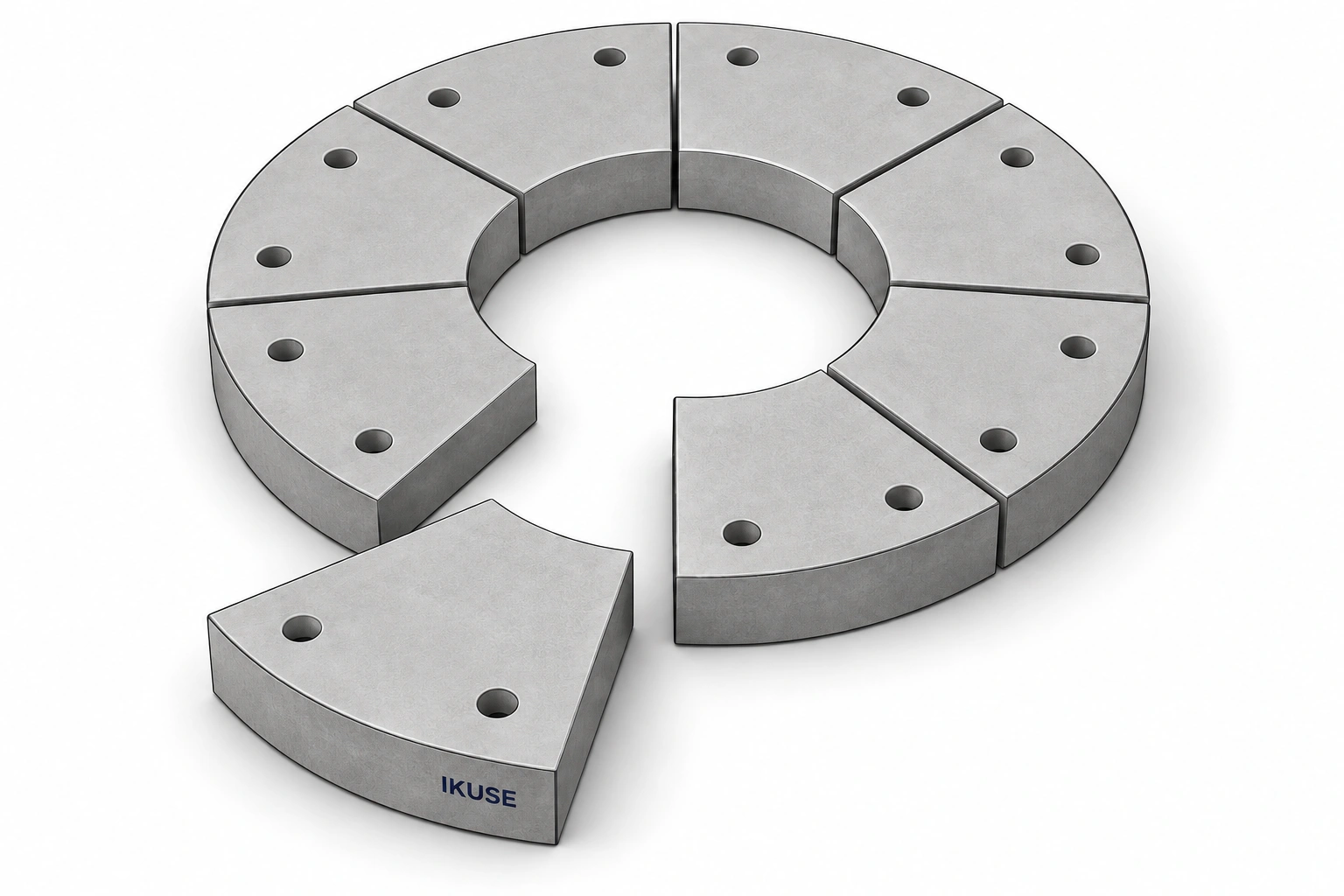
Wear-protection liners for mill ends, including sector-shaped segments and concentric arrangements. Geometry depends on feed or discharge location, segment angles, fixing holes and adjoining components.
Design and configuration
Check inner and outer contours, sector angle, ring position, thickness and joint clearances. Verify each part number and quantity against the complete layout. Similar individual outlines do not establish interchangeability.
Mill liners and grinding media · Application
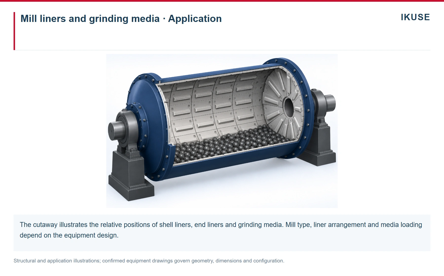
The cutaway illustrates the relative positions of shell liners, end liners and grinding media. Mill type, liner arrangement and media loading depend on the equipment design. Structural and application illustrations; confirmed equipment drawings govern geometry, dimensions and configuration.
Operating conditions and installation
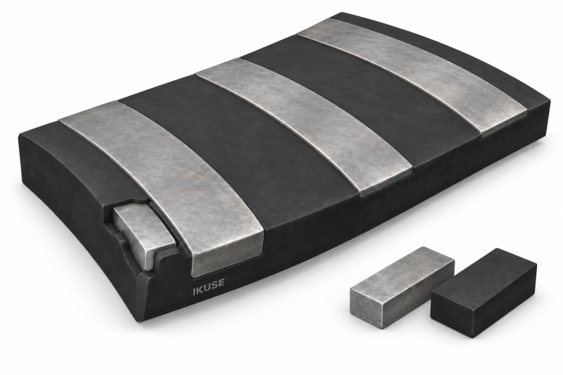
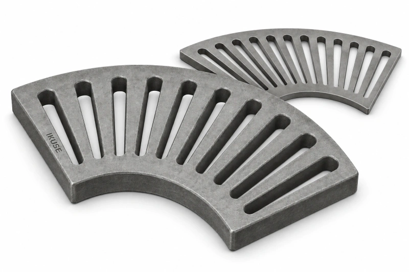
Backing support, holes and fasteners must match the mill end. Solid protective liners, discharge grates and diaphragm components have different functions and interfaces, even when all have sector-shaped outlines.
Inspection and maintenance
Record wear location, remaining profile, impact marks, local damage, support and fixing condition. Reassess the lining when feed, media size or operating mode changes. For composite liners, also inspect rubber and interfaces.
Information for enquiries
Provide end assembly and layout drawings, ring positions, part numbers and quantities, working-face and back-face photographs, hole and fastener details, material duty and the locations of existing wear.
Product illustration
Illustrations show typical structural arrangements. Materials, dimensions, interfaces and supply scope are subject to the approved drawings and technical documents.